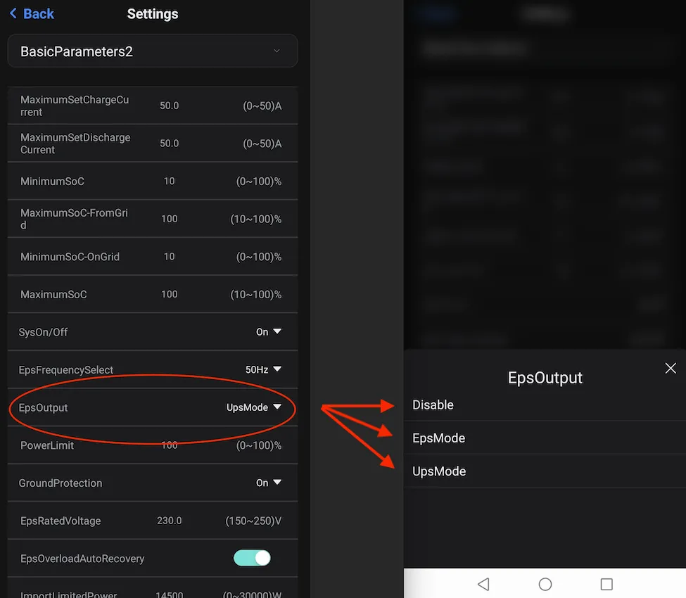
EPS v UPS
What is the difference between EPS Mode and UPS Mode?
Section titled “What is the difference between EPS Mode and UPS Mode?”EPS Mode stands for Emergency Power Supply Mode. What this means technically is that the EPS port on the inverter is only live when there is no grid power. UPS Mode means Un-interruptable Power Supply Mode and this means that the EPS port on the inverter is constantly at 240v all the time. (It doesn’t help that EPS is the word used to also reference where the backup power is coming from).
There is a setting in the app (and also in the inverter) to toggle between these two modes but usually by default, the UPS mode is active. This means that if you measure between the red EPS conductor and neutral or earth, you’ll see a constant 240v regardless of whether you have grid power or not.
Why have a difference between the two?
Section titled “Why have a difference between the two?”This is where it gets interesting. Some may think that it is non-sensical to have the EPS wire hot or live 24/7. Why not just activate it when the grid is down? Wouldn’t that make more sense? Yes and no and here is why.
The installation guide shows this set up for AC wiring.
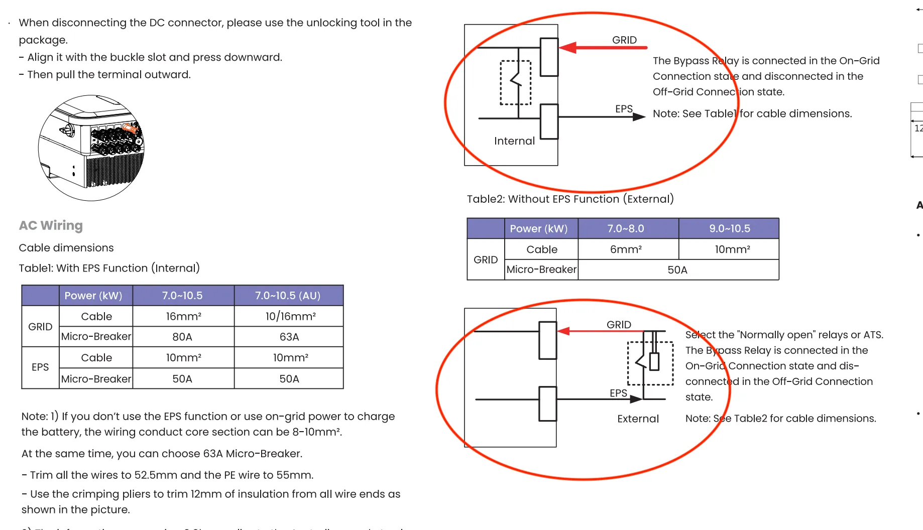
Figure 1: Internal v external EPS function
This image is not immediately self explanatory but what it is trying to say is that the cable size to use between the inverter and the main switchboard depends on if EPS is included in the overall design and if it is, will it be configured internally or set up externally.
Back to basics
Section titled “Back to basics”If you look at the datasheet for say the KH10 Fox ESS inverter you will notice that the Max AC Output current is 45.7A and the Max Input AC current is 63A for Australia. The EPS max current is 45.5A.
The Max AC Output current of 45.7A is saying that the inverter can pump out a max of 45.7A to send back to the grid or to supply the house. The Max Input AC current is saying that the inverter can pull in a max of 63A from the grid to charge the batteries and/or supply power to the EPS load.
So how do you cable size for this? This is where AS/NZS 3008 comes in and if you look table 4 you’ll see 10mm can handle about 54A with derating not even factored in yet. The next cable size up is 16mm 2C+E which is quite large, expensive and more difficult to work with. So what do you do?
Does the customer want back up?
Section titled “Does the customer want back up?”You ask the customer if they want back up. If they don’t, then the documentation says 10mm cable can be used because the AC Input current is not longer 63A. It is lower because no current will be used for the EPS.
If the customer wants backup, then you need to decide how you want to configure it. Internally or externally.
Internal EPS v External EPS
Section titled “Internal EPS v External EPS”In a nutshell, if you want the Fox inverter to handle the back up then you’ll need a thicker cable. If you handle the backup yourself, aka externally with a transfer switch, then you can use a smaller cable. This explains why in most cases, a 10mm cable is used with a 50A breaker for the GRID cable.
At a deeper level, when the Fox internal EPS function is utilised, battery charging current AND EPS current needs to be supported on the one cable between the inverter and the switchboard.
IF the EPS is configured externally, the there are 2 separate paths or cables or conductors. Battery charging current on one cable and EPS current on a totally separate cable. This means that the “GRID” cable can be sized much smaller. 10mm in this case on a 50A breaker as can be seen in Figure 1.
How to set the Fox inverter to internal or external EPS?
Section titled “How to set the Fox inverter to internal or external EPS?”3 phase system
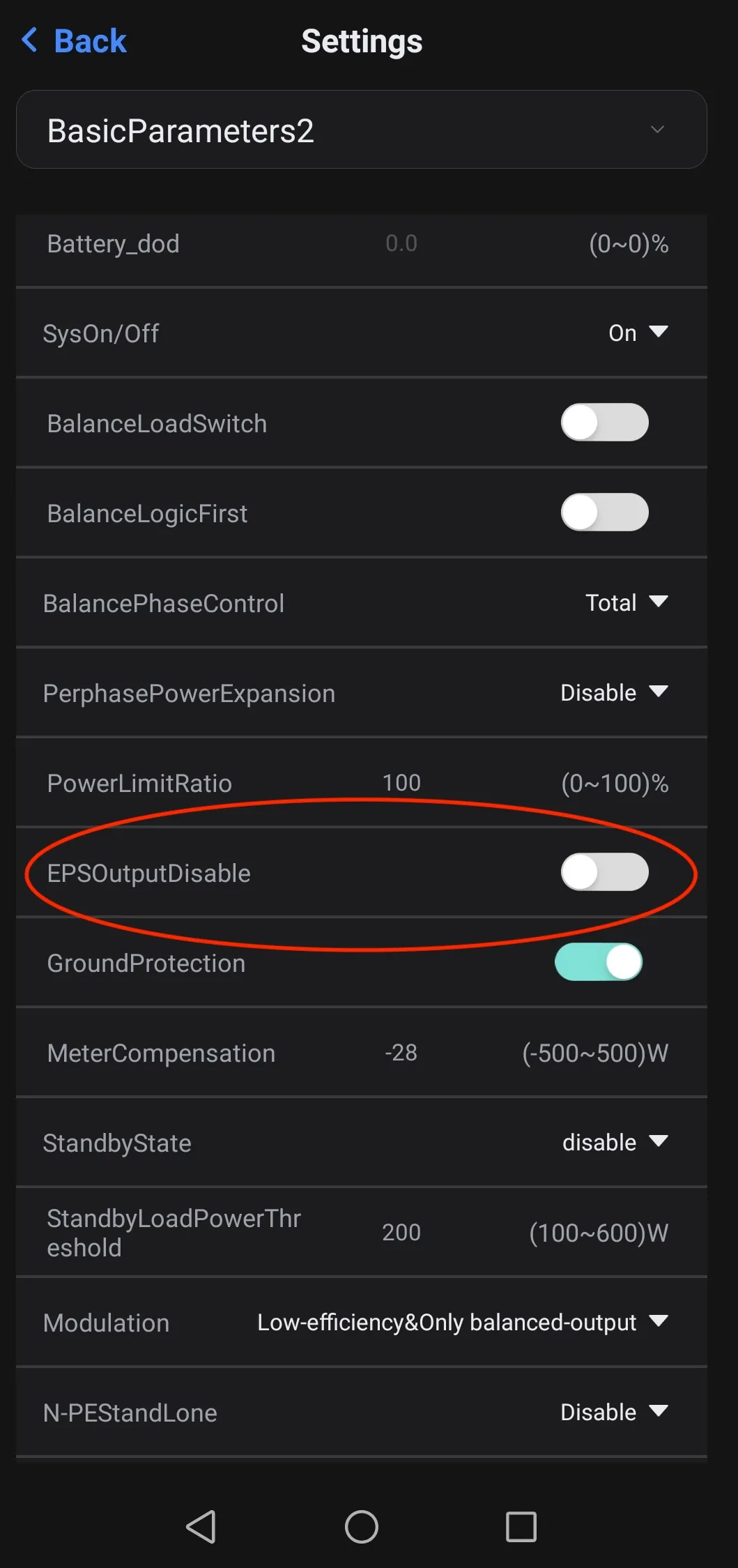
Section titled “3 phase system”For a 3 phase system, under inverter settings > BasicParameters2 you should see an EPSOutputDisable toggle.
EPSOutputDisable = OFF means false so that EPS Output is NOT disabled which means EPS output is enabled. If the EPS is enabled, this means that the EPS port will only be live when there is a grid failure. This means that the design now relies on the internal inverter EPS function to know when there is a grid failure and liven the EPS port. Utlising the internal inverter EPS function means that a much larger cable needs to be used. All this is to say that this setting is very important because it has a big say in what size cable to use.
Single phase
Section titled “Single phase”For a single phase system, it is much less ambiguous because there is a drop down where you can select the the EpsOutput to either:
- EpsMode - EPS is only live when there is a grid failure
- UpsMode - EPS is live 24/7 regardless of grid status
- Disabled
The standard practise most installers use is UpsMode to allow a smaller cable size (10mm) to be used as per the installation manual. An external transfer switch is then required to handle backup if desired.